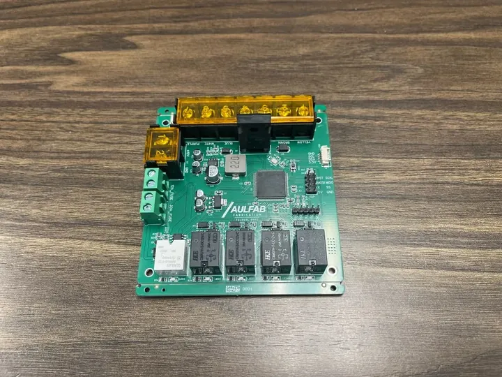
Trailer control box
How CircuitNexa consolidated a wire-heavy, multi-module trailer prototype into a single trailer control PCB for AULFAB, covering lighting, electric brakes, power management, and load monitoring.
The challenge
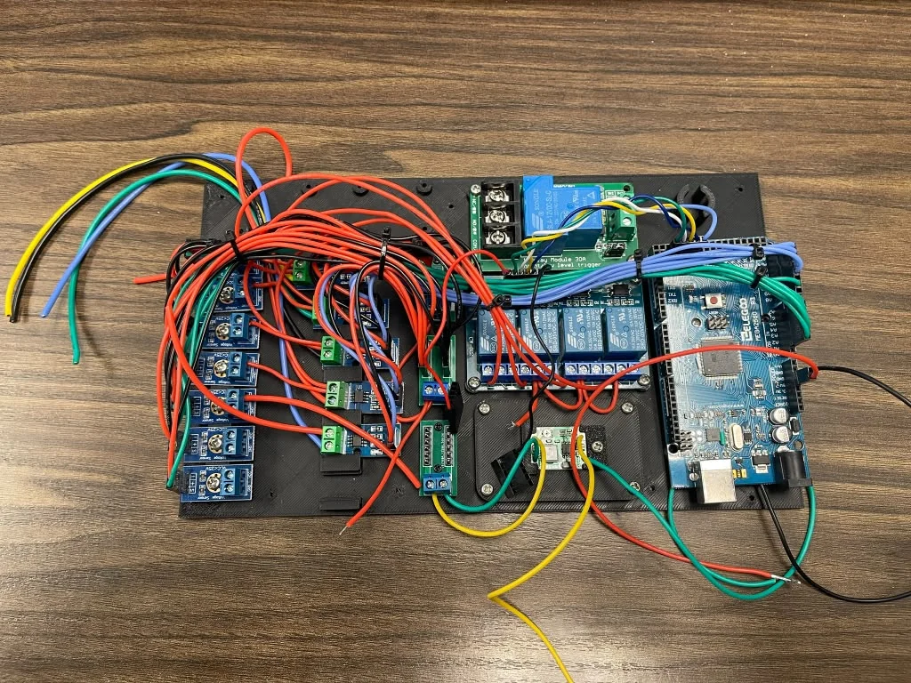
AULFAB's trailer electronics started as a prototype built from several separate modules connected by extensive wiring. The goal for CircuitNexa was to consolidate those functions into a structured, dedicated control PCB, while adding electrical monitoring and protection capabilities.
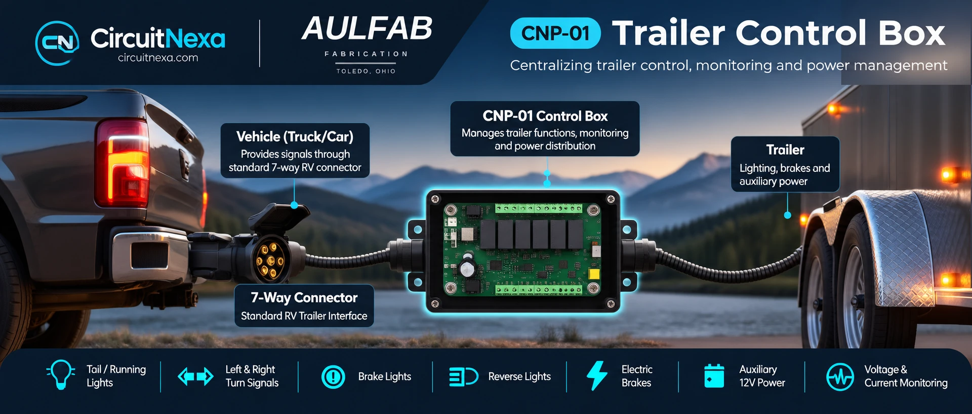
The system connects to the towing vehicle through a standard 7-way RV trailer connector and has to handle the trailer's lighting and braking functions from one place.
The hard part was never switching trailer lights. It was bringing high-current loads, 12V automotive and trailer power, embedded control, current sensing, voltage measurement, and external communication together on a single PCB, where each one puts different demands on the layout. That meant working through a set of design considerations at once:
- High-current paths and power distribution
- Relay selection and routing
- 12V-to-5V conversion for the logic supply
- Current sensing, voltage measurement, and ground-sense monitoring
- Controller interfaces and connector organization
- PCB layout, protection, and reliability
The 7-way trailer connector
The board interfaces with the towing vehicle through the standard 7-way RV trailer connector. Each wire carries a fixed function, and the board's terminal block is marked with wire-color labels:
| Wire | Function on the 7-way connector |
|---|---|
| Brown | Tail / running lights |
| Red | Auxiliary 12V power |
| Green | Right turn signal / brake light |
| Purple | Reverse lights |
| Blue | Electric trailer brakes |
| White | Ground |
| Yellow | Left turn signal / brake light |
On top of switching, the board provides individual voltage monitoring and load-current monitoring, plus a ground-sense check on the trailer body, so the state of each output can be observed rather than assumed.
The main 12V battery supply enters through a dedicated terminal connection, and the board generates the 5V logic supply for the controller and supporting circuitry from it. Dedicated terminals are marked for 10A and 30A fuses.
Electronics architecture
Main controller
An ATmega2560, the same microcontroller family used on the Arduino Mega, controls the relay outputs, monitors electrical parameters, and communicates with the display module.
Load switching
Five relays switch the trailer loads, using 15A-rated channels for the lighting and control functions and a 30A-rated channel for the electric brake load.
Current monitoring
ACS712 current sensors measure current through the relevant relay and load paths. That lets the system watch the electrical behavior of individual outputs, not just turn them on and off.
Voltage monitoring
Resistor-divider networks scale selected 12V signals down to levels the controller can measure.
Ground-sense monitoring
A ground-sense electrode is connected to the trailer body, and the board measures its voltage continuously. A properly grounded trailer should read 0V. If the reading is anything else, for example 12V, the system raises an error for the user.
Display and communication
The prototype talks to an external ESP32-based OLED display module over I²C, which presents the monitored electrical information to the user. The PCB has a dedicated I²C header for that connection and an ISP header for programming the microcontroller.
Development process
- Existing prototype analysis. Reviewed the module-based system and its wiring and interfaces.
- System architecture. Mapped the 7-way trailer connections, power architecture, relay channels, monitoring requirements, and controller interfaces.
- Schematic design. Designed the control, power, relay, current-sensing, voltage-sensing, and communication circuitry.
- PCB design. Integrated the system onto a dedicated PCB with high-current routing, connectors, and component placement suited to the loads.
- Manufacturing. Generated manufacturing-ready PCB data and produced the first hardware iteration.
- Hardware bring-up. The first manufactured prototype has been received and is progressing through bring-up and validation.
Where it stands today
The first manufactured prototype has been received and is progressing through hardware bring-up and validation, so the project currently sits at: designed, manufactured, in bring-up.
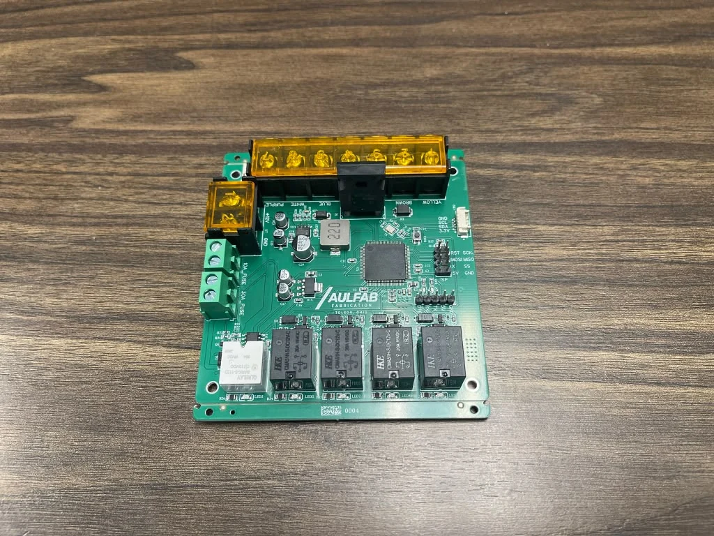
This write-up describes the design and its current stage. It should be read as a hardware case study, not a field-validation report, and it makes no claim that the system is fully validated or production-ready. What the first iteration does show is the shift from a multi-module, wire-heavy prototype to a dedicated control-board platform.
Planned V2 direction
The next iteration is planned to simplify the system further by replacing the ATmega2560 and external ESP32/OLED arrangement with an integrated, ESP32-based standalone controller and display architecture. If it goes as intended, control, communication, monitoring, and display would sit on one more compact platform, with fewer major modules than the current design.
What this demonstrates
This project is representative of the automotive PCB design and embedded hardware work CircuitNexa takes on: boards where high-current switching, embedded control, and measurement have to coexist, and where the real job is turning a multi-module prototype into a single, structured platform. The value is less in any one component and more in how power distribution, relay selection, current sensing, and layout are resolved together.
Building automotive or power electronics?
CircuitNexa helps startups and engineering teams turn electronics concepts into manufacturable hardware.
Talk to CircuitNexa